

Get a Free Quote

Our representative will contact you soon.
Email
Mobile
Name
Company Name
Message
0/1000
Industries
Home> Industries

AUTOMOTIVE

AUTOMOTIVE
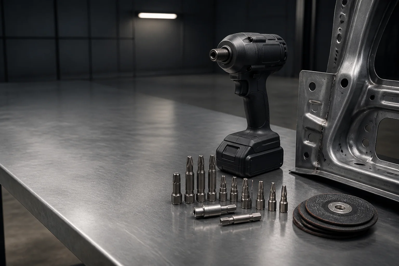
Automotive assembly workbench with a cordless impact driver, hex-shank driver bits and a stamped steel panel
Automotive

Automotive tool accessories that hold torque and hole tolerance at line speed.

Impact-rated bits and drills specified for repeat-cycle rundowns, hardened spot welds and plated fasteners.

Get a Quote in 24 h Request a Free Sample

An assembly station does not buy a drill bit. It buys the rundowns between tool changes, and a hole that lands inside the drawing tolerance on the first attempt. This page answers that brief in parts: which drive geometry, which point geometry, which substrate decision, and which public standard stands behind each claim. Every specification is written so that a manufacturing engineer can check it against a drawing or a standard rather than against a supplier's adjective.

Industry snapshot

Four variables that decide the outcome

Four variables decide whether a consumable survives an automotive line: the tool driving it, the material it cuts, the standard it must fit, and the way it fails once the edge is gone.

Typical equipment
Pneumatic impact wrenches, air ratchets, DC electric nutrunners, right-angle drills, spot-weld drills, robotic fastening cells.
Materials processed
HSLA and press-hardened boron steel sheet, 6xxx-series aluminium panel, zinc-nickel plated fasteners, ABS and PP trim clips, resistance spot welds and their heat-affected zone.
Governing standards
DIN 3126 / ISO 1173 for bit drives, DIN 338 for twist drills, ANSI B94.11M for drill point geometry, ISO 2725-1 for square drives, ISO 286-1 for fits, ISO 6508-1 for hardness, ISO 9227 for corrosion testing.
Failure modes seen
Drive-end rounding, cutting-tip chipping on spot welds, socket wall deformation, cam-out, shank fracture, thread stripping in aluminium, black-oxide breakdown under continuous coolant.
Operating challenges

Three failures that cost lines money

Each challenge states what goes wrong, then the geometry or material decision that answers it.

Challenge 1

High-torque fastening rounds off the drive end.

A station repeats rundowns until the drive corners of the bit are worn, and the bit reaches its limit before the tool does. Where the drive rounds within a shift, the fastener is no longer driven with the geometry the joint was specified around: the bit begins to cam out before it stops transmitting torque, so the cycle is recorded as complete while the torque actually delivered to the joint is no longer the torque the drawing asks for. The operator notices the slip before quality does, which means the failure is usually caught at the station rather than in the audit — but the change still interrupts the cycle.
Amsuo response

Drive-end rounding → Quick Change Hex Shank Drill Bits and Screw Driver Bits.

The drive geometry is ground rather than forged, so the contact patch between bit and holder stays constant across repeated cycles instead of progressively deforming, and there is no forged flash to smear during the first rundowns. The steel is heat-treated through the torsional section rather than cased only at the surface, which keeps the shank uniform along its length so the bit absorbs shock torque instead of transferring it to a single corner.
Challenge 2

Spot-weld drilling destroys ordinary tips.

The weld nugget and its surrounding heat-affected zone are locally hardened, so a drill crosses an abrasive skin at entry and then re-enters softer parent metal. A general-purpose tip dulls or chips on that transition. Where the tip loses its cutting edge, the drill is scrapped before it is worn out, and the thrust needed to keep cutting rises, which pushes the operator to lean on the tool and shortens the life of the machine side of the joint.
Amsuo response

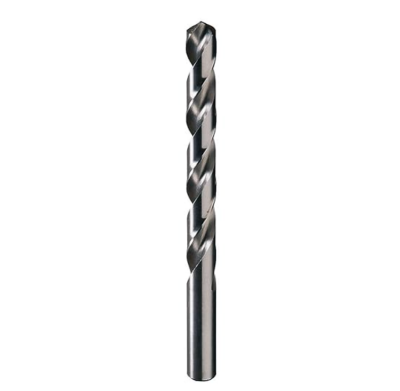
Hardened spot welds → Drill Bits in a carbide-tipped form.

A split point distributes thrust across two cutting lips and thins the chisel edge, removing the dead zone at the centre of the hole so the hardened weld skin is cut instead of pushed. The point geometry is specified for drilling through a hardness transition rather than uniform mild steel, and the family is supplied in stub and long-series lengths so that access between panel flanges does not force a compromise on point shape.
Challenge 3

Mating surfaces get marked.

An impact socket that bears on the plated flat of a fastener leaves witness marks on the hex. At incoming inspection a witness mark is a cosmetic reject on a functional part, so the assembly is reworked or scrapped even though the joint itself is sound. The constraint is not torque capacity, which is easily met; it is controlling where the socket is permitted to touch the fastener.
Amsuo response

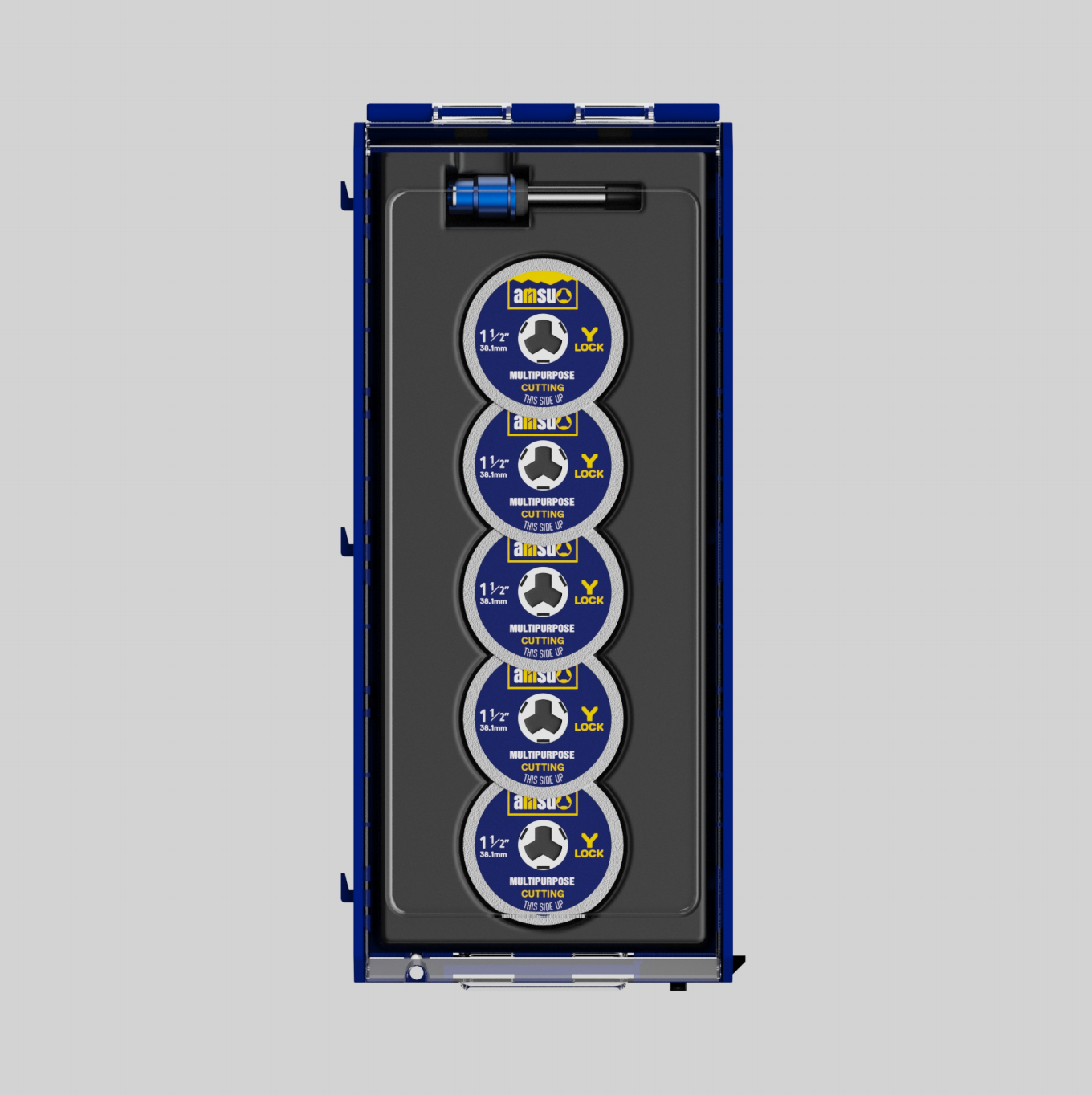
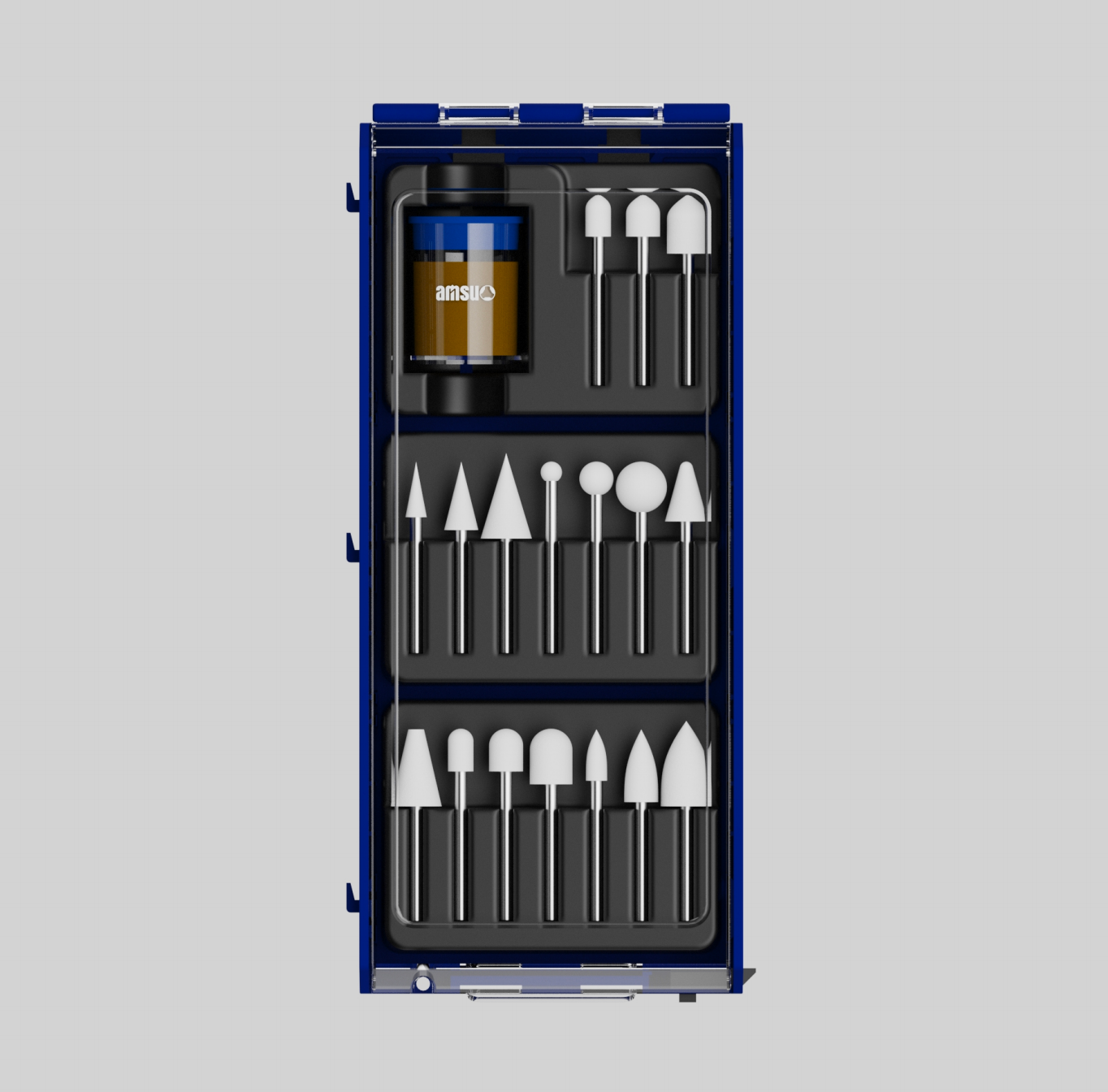
Surface marking → Power Tools Accessories Sets specified around the fastener interface.

Where a socket bears on the finished flat, the load path is moved onto the fastener flank, so the cosmetic surface is not the surface that carries the drive. Wall sections are dimensioned so the hex opening returns to nominal after each cycle instead of opening up progressively, and finishes are chosen for the environment the socket actually sees: where a station runs continuous coolant, black oxide is replaced by a treatment selected to hold up under the neutral salt spray conditions of ISO 9227.
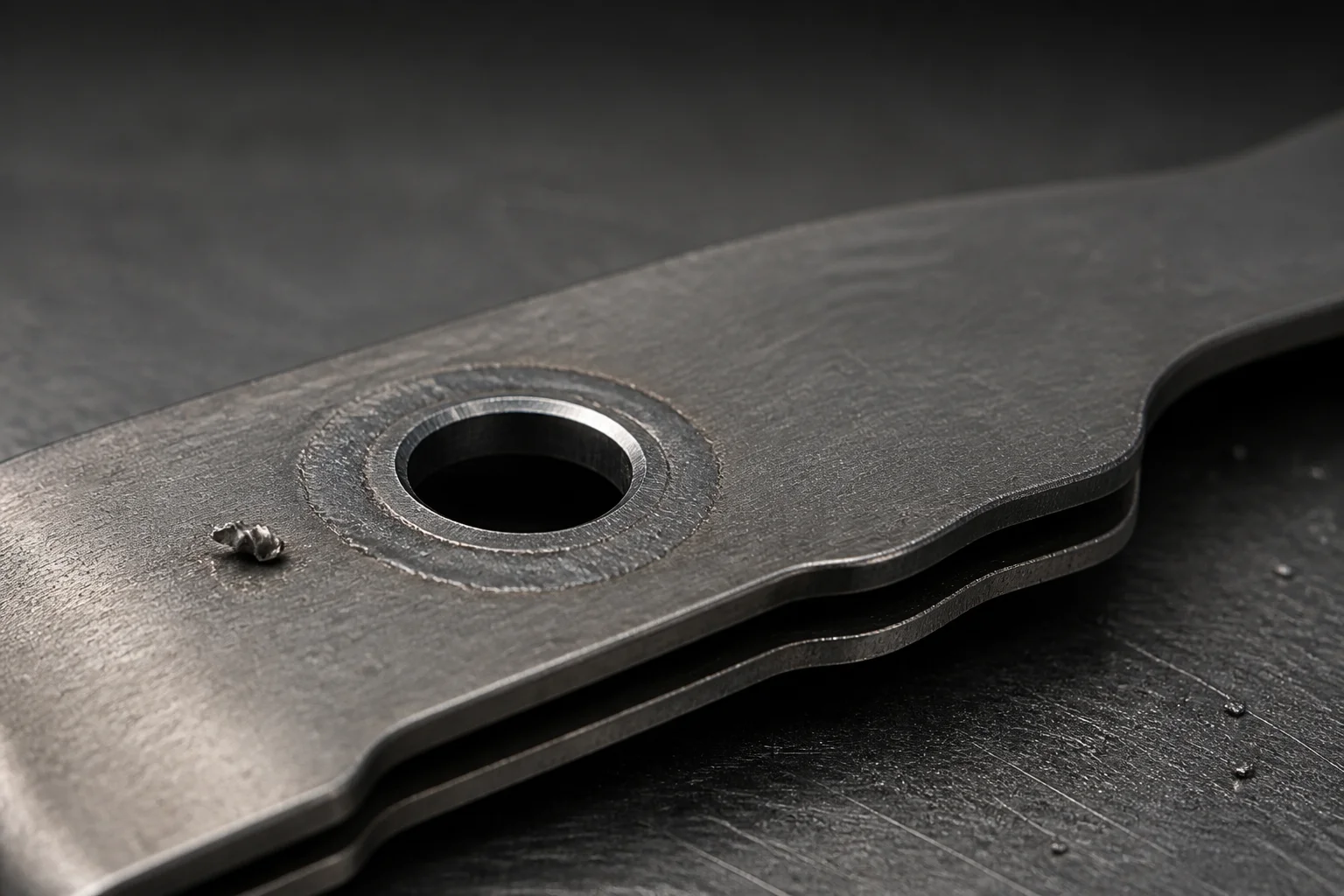
Macro view of a drilled hole through a spot weld joining two stamped steel sheets
Product families

The families that map to this application

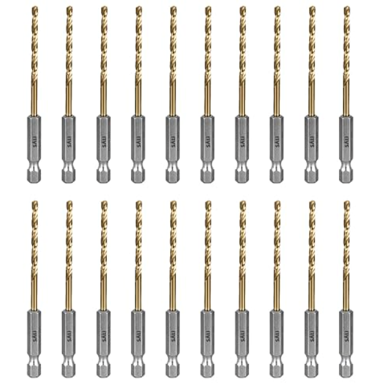
Quick Change Hex Shank Drill Bits

Quick Change Hex Shank Drill Bits

Drive bits and shanks changed at the station without a chuck key

Answers: Drive-end rounding and slow tool change

Standard: DIN 3126-C 6.3 / ISO 1173

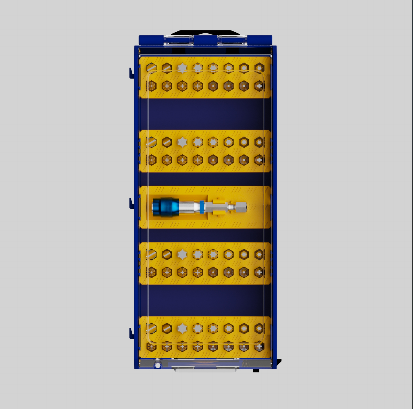
Screw Driver Bits

Screw Driver Bits

Repeat-cycle rundowns on plated and painted fasteners

Answers: Cam-out and drive corner wear

Standard: DIN 3126-C 6.3 / ISO 1173

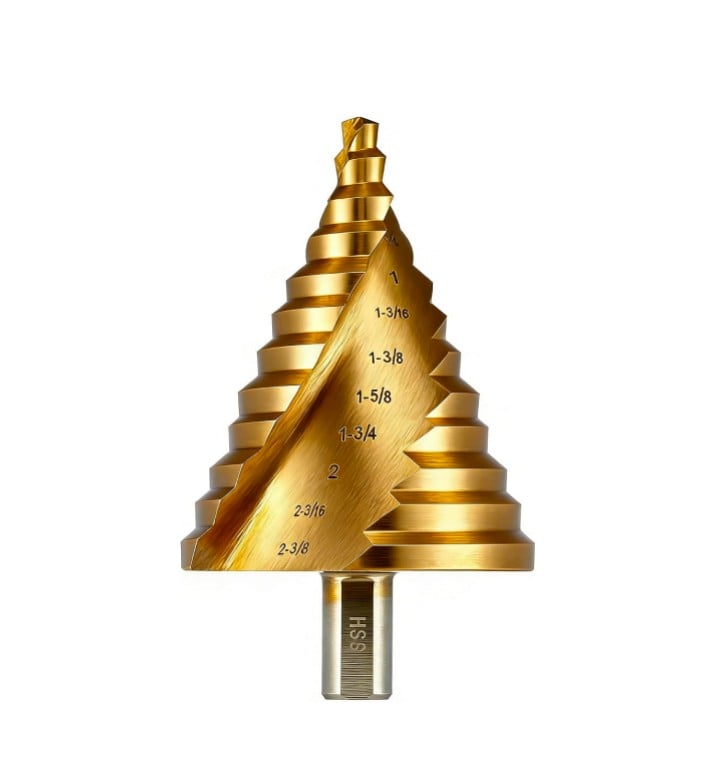
Drill Bits

Drill Bits

Drilling through panel, weld and flange material

Answers: Tip chipping on hardened weld skin

Standard: DIN 338

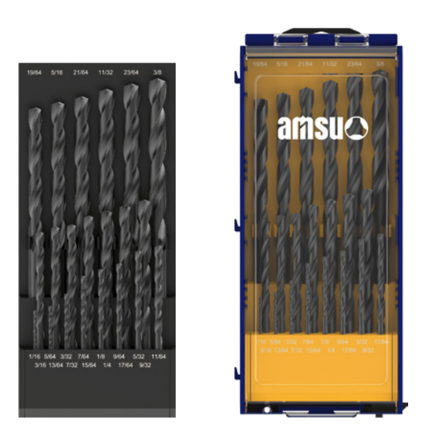
Drill Sets

Drill Sets

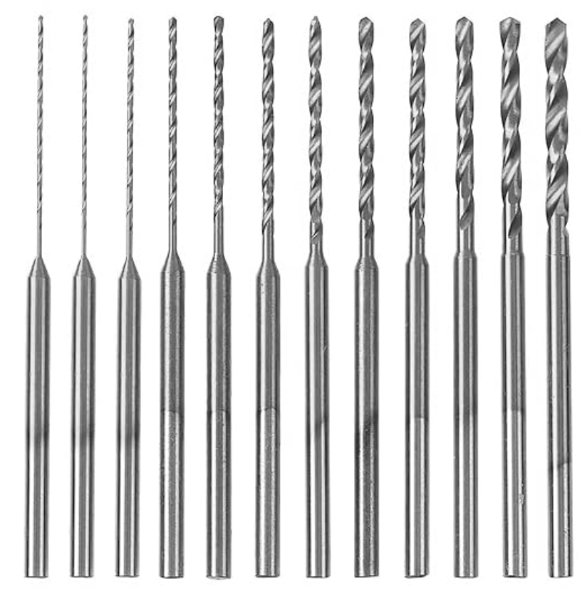
Line-side replacement of worn diameters

Answers: Unplanned station interruption

Standard: DIN 338

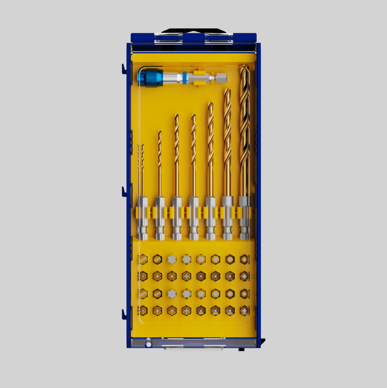
Drill & Driver Combination Sets

Drill & Driver Combination Sets

Drilling and fastening kitted for one station

Answers: Tool mismatch at the station interface

Standard: DIN 3126-C 6.3 / ISO 1173

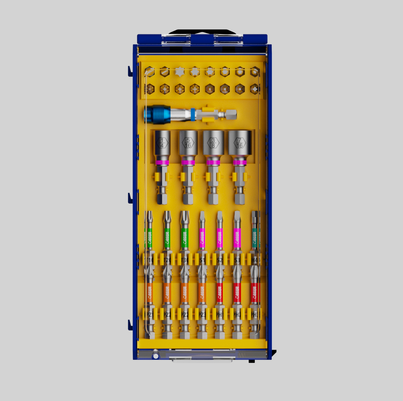
Power Tools Accessories Sets

Power Tools Accessories Sets

Accessories grouped for retail and line-side programmes

Answers: Interface wear between tool and accessory

Standard: ISO 2725-1

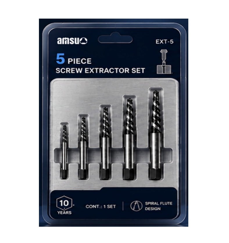
Screw Extractors

Screw Extractors

Removing broken or stripped fasteners

Answers: Thread stripping and fastener head damage

Standards & specification

The numbers behind the claims

The table names the parameter, the standard that fixes it, and why a plant's quality function checks it.

Parameter Reference standard What the standard fixes Why the buyer checks it
Bit drive geometry DIN 3126-C 6.3 / ISO 1173 The form and dimensions of the driving square and the hex drive ends The bit must engage the holder the line already uses, not a near fit
Twist drill dimensions DIN 338 Diameter series, shank and flute proportions of parallel-shank twist drills A replacement drill must be dimensionally interchangeable with the one it replaces
Drill point geometry ANSI B94.11M Point angles and the split-point form for twist drills Point shape governs thrust, wander and the load at breakthrough
Square drive fit ISO 2725-1 The driving square dimensions of socket-type attachments An attachment that is not to the standard damages both tool and fastener
Fit of shanks and holders ISO 286-1 The ISO tolerance system of limits and fits The fit class decides whether the tool is concentric and whether it pulls out
Geometrical tolerancing ISO 1101 How form, orientation and position tolerances are expressed Allows a drawing call-out to be measured the same way by both parties
Hardness testing ISO 6508-1 The Rockwell hardness test method and its verification A hardness figure is only comparable when the method is named
Corrosion testing ISO 9227 The neutral salt spray test procedure Surface treatments are compared on a stated exposure method, not a description
How we verify

Organised around method, not around a published figure

Our inspection is organised around method category rather than around a published figure. Dimensional and geometrical checks use the instrument appropriate to the call-out and are read against the standard that fixes the dimension: DIN 338 for drill proportions, ISO 286-1 for fit classes, ISO 1101 for form and position, and ISO 2768 where a drawing is not otherwise toleranced. Hardness is checked by the method named in ISO 6508-1, and a surface treatment is assessed against the corrosion test procedure in ISO 9227 where a coating is specified for a wet or coolant-exposed station.

Batch-level traceability links a finished lot to the material certificate for the steel it was made from, so a question raised against a delivered box can be answered by going back to the steel rather than to a memory of the run. Tooling and processes sit inside a three-system management framework — quality, environmental, and occupational health and safety — certified to ISO 9001, ISO 14001 and ISO 45001. Where a buyer's quality function asks for records beyond the batch report, the relevant documents are provided on request. Where an inspection is not applicable to a given family — a coating test on an uncoated bit, for example — we say so rather than issuing a result for an operation that was not performed.

ISO 9001
Certified management system
ISO 14001
Certified management system
ISO 45001
Certified management system
Customization & delivery

Three levels of engagement, one sequence

Orders in this application arrive in three shapes.

Level 1 — Private label
the buyer's brand goes onto tooling that is already qualified, so the drawing does not move and any existing qualification stays valid.
Level 2 — Packaging & specification
the pack count, retail layout, barcode and agreed specification changes are built around the same qualified tooling: the usual route for a retail programme, where the carton carries as much commercial weight as the bit.
Level 3 — Sample- and drawing-driven
new tooling is produced from the buyer's sample or drawing, and a design-for-manufacture review is returned before any tooling is committed, so geometry questions are settled on paper rather than in the first article.The sequence is the same at all three levels. The requirement is fixed in writing — drive form, point geometry, material class, finish, pack format; the drawing or sample is reviewed; a manufacturing route is confirmed against the tolerance that has to be held; a first-article inspection is made against that drawing; and the lot is released with a batch record. A change after approval restarts from the revised drawing, and we say so at the time rather than at the delivery date. Packaging engineering is included wherever the buyer's planogram governs the pack.
Buyer questions

What purchasing teams ask first

What does a bit or socket cost, and what drives the price?

Unit price is quoted per line item and depends on the material grade, the finish, the tolerance band requested and the pack format. We do not publish a list price, because the same shank can be supplied in more than one hardness band at more than one cost. Send the drawing or the sample together with the annual quantity, and a quotation is issued against that basis.

What is the smallest quantity for a custom socket or a new bit geometry?

We quote from the drawing rather than from a catalogue minimum, because the entry quantity is set by the tooling a geometry needs rather than by the order size. A change to wall thickness or shank length stays close to the standard route, while a new drive profile needs its own tooling and is quoted on that basis. The two cases are separated in the offer so the buyer can see which cost belongs to which.

Can we get samples before committing to a production order?

Yes. Samples are drawn from the qualified tooling for the range involved, and a first-article inspection report travels with them, so the trial result can be compared against a stated drawing rather than against a memory of the previous supplier's bit. Where a line trial is planned, tell us the acceptance criterion in advance and the sample is quoted against it.

What is the lead time from drawing to first article, and then to production?

Drawings are reviewed on receipt, and the first article follows once the route and the coating schedule are confirmed; production starts after the sample is signed off. Coating is a separate step in the sequence and sits on the critical path, so where a station depends on a specific date the coating schedule is the point to confirm at the order stage rather than after the tools are made. If the review returns a geometry change, the clock restarts from the revised drawing.

Which inspection documents accompany a shipment?

Every shipment carries a batch inspection record covering hardness and the key dimensions on the drawing, together with the material certificate for the steel lot. Where the tool is coated, the surface treatment is recorded against the relevant standard. Families subject to additional testing have those records held per family and issued on request.

Ready to specify it?

Send us the failure, not only the drawing. Tell us what breaks, at which point in the cycle, and on which material, and we will state which geometry, material or finish decision answers it — including when we are not the right supplier for the job.

Get a Quote in 24 h Request a Free Sample

Get a Free Quote

Our representative will contact you soon.
Email
Mobile
Name
Company Name
Message
0/1000