

Get a Free Quote

Our representative will contact you soon.
Email
Mobile
Name
Company Name
Message
0/1000
Industries
Home> Industries

AVIATION

AVIATION
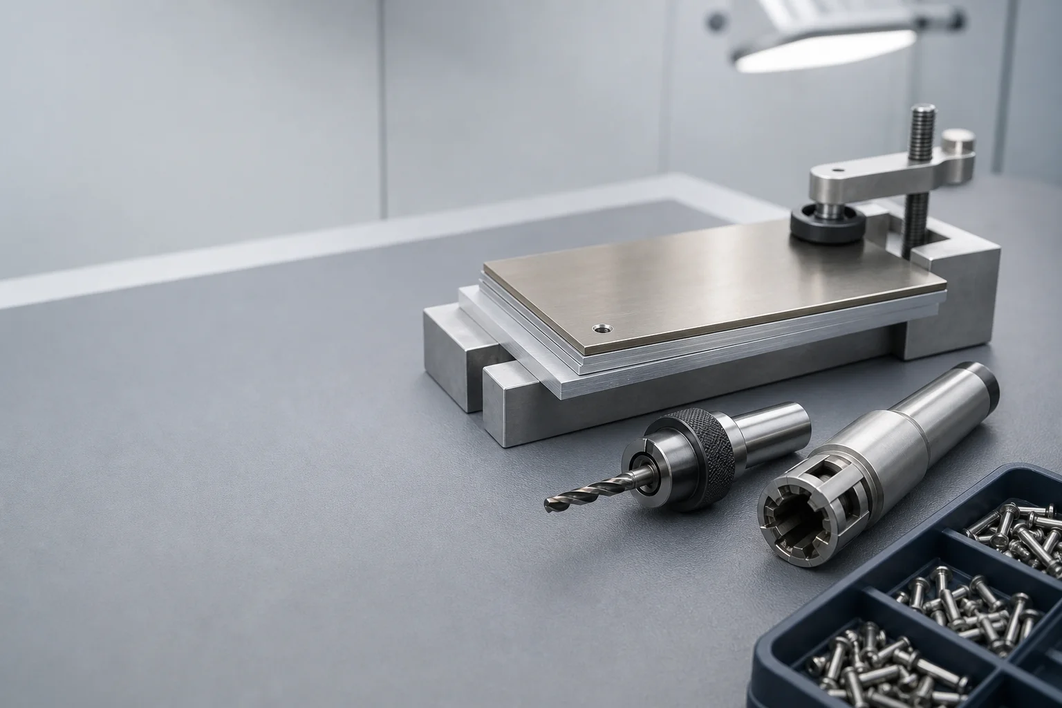
Aerospace assembly bench with a clamped titanium and aluminium sheet stack, a stub-length precision drill and a tray of close-tolerance fasteners
Aviation

Aviation tool accessories that hold hole size through carbon, titanium and stack material.

Drills, deburring tools and accessories specified by stack sequence and hole tolerance class.

Get a Quote in 24 h Request a Free Sample

An aerospace hole is judged twice: once on the diameter it finishes at, and once on the damage it left behind in the material. A drill that holds diameter in aluminium can delaminate the last plies of a carbon laminate, and a geometry that runs cool in aluminium can burn the titanium face of a stack. This page states which substrate, coating and point geometry is specified for each stack sequence, and the basis on which each selection can be checked.

Industry snapshot

Four variables that decide the outcome

Aviation work is defined by the mix in the hole rather than by the hole itself: a single fastening location may pass through carbon laminate, adhesive, titanium and aluminium before it exits. Tooling is therefore selected against the whole sequence, which is why a specification written for one material in the stack will not survive the others.

Typical equipment
Automated drilling units and orbital drilling heads, gantry routers for panel trim, pneumatic hand drills with microstop countersink cages, rivet guns, torque-controlled nutrunners, robotic wing-panel cells.
Materials processed
CFRP laminate, CFRP and titanium stacks, CFRP and aluminium stacks, Ti-6Al-4V, 7075-T6 and 2024-T3 aluminium, 15-5PH stainless, A286, Inconel 718, aluminium honeycomb core, glass fibre composite.
Governing standards
AS9100 for the quality system the order runs under, ANSI B94.11M for drill point geometry, NAS 907 and ISO 5855-1 where the drawing calls them, ISO 286-1 for the fit, ISO 1101 for geometrical tolerancing, ISO 4287 for surface texture, ISO 6892-1 for tensile testing, ASTM E384 for microindentation hardness, ASTM E466 for axial fatigue, ASTM B117 for salt spray, ISO 9712 for non-destructive testing personnel, ASTM E1417 and ASTM E1444 for penetrant and magnetic particle inspection.
Failure modes seen
Exit delamination and push-out burrs in CFRP, oversize holes from drill wander, alpha case formation on Ti-6Al-4V, flank wear at high cutting temperature, galling on aluminium, edge chipping as the point crosses from laminate into titanium, burr height above drawing limit, hole position error from long-reach whip.
Operating challenges

Three failures that cost lines money

Each challenge states what goes wrong, then the geometry or material decision that answers it.

Challenge 1

CFRP delaminates at the exit while the drill is still cutting.

As the point breaks through the last plies, axial thrust pushes the uncut laminate away from the tool instead of shearing it, and the plies separate. A hole that is delaminated but still within diameter fails inspection, because the damage is measured separately from the fit, so the consequence is a repair rather than a re-drill. The failure starts on the exit side, which is also the side the operator cannot see while drilling.
Amsuo response

Exit delamination in CFRP → Drill Bits in solid carbide with a diamond coating.

A diamond film holds its hardness against the abrasion of carbon fibre far beyond what an uncoated edge manages, so the cutting geometry stays as ground for the whole batch rather than wearing into a different shape. Point geometry is set to keep axial thrust low at the moment the tip approaches the exit plies, and the outer corners are positioned so the last fibre layers are sheared against a supported surface instead of being pushed. The same geometry is available with through-coolant and with a microstop shank, so hand drilling uses the same point at the same nominal diameter.
Challenge 2

One geometry has to cross from carbon into titanium mid-hole.

Carbon fibre is abrasive and carries heat away with the chip only slowly, while titanium is chemically reactive and holds heat at the edge. Where a geometry that survives the laminate meets the metal interface, the flank wears quickly; where the edge is made strong enough for titanium, it tends to push the carbon plies rather than shear them. Running a tool to the end of its life inside a stack also means the next hole is cut with an edge that has already changed size, which is how a hole inside tolerance drifts oversize and needs a rework pass.
Amsuo response

Stack drilling → Drill Bits with a multi-layer coating and a defined edge hone.

The coating carries the cutting temperature away from the edge in titanium, so the substrate is not exposed at the temperature where flank wear accelerates, and the layer arrangement places a tougher layer under the harder one to resist the impact at the laminate-and-metal interface. The edge hone radius is held at a figure that keeps the point from micro-chipping on the transition between the two materials, and internal coolant holes direct fluid at the point, which is the practical way to control titanium temperature once the hole is deeper than the drill diameter.
Challenge 3

Titanium burns and aluminium galls, at two different temperatures.

In Ti-6Al-4V, an edge temperature above the safe band produces rapid flank wear and a hardened, oxygen-enriched layer at the hole wall that has to be removed before the fastener can be fitted. In aluminium, the same tool run at the same feed builds material up on the rake face and transfers it to the hole wall, so the surface tears and the reamed size closes down. Two materials, two mechanisms, and one drill that has to survive both without a mid-part tool change.
Amsuo response

Galling on aluminium and hole-wall damage in titanium → Burrs and edge-blending tools matched to the material.

For aluminium, the cutting face is polished and left uncoated, because a coating raises friction against a soft, reactive workpiece and becomes the surface the aluminium welds to. For titanium, the hole wall is protected by controlling edge temperature rather than by the coating alone, which in practice means a specified cutting speed band and a feed high enough to keep the edge out of the rub-and-burn regime. Deburring follows the same logic as drilling, because a burr removed with the wrong geometry leaves a mark that has to be inspected again. Both families are ground to an h6 shank in the tolerance the drawing calls for, so the fit in a microstop cage or an automated unit is repeatable from tool to tool.
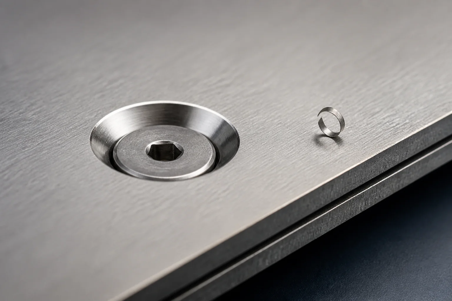
Macro view of a countersunk hole through a clamped metal stack with a flush fastener head
Product families

The families that map to this application

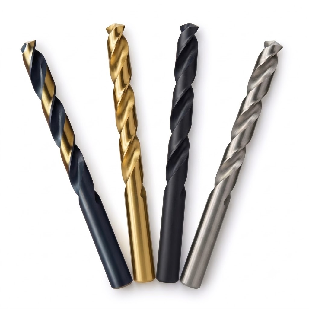
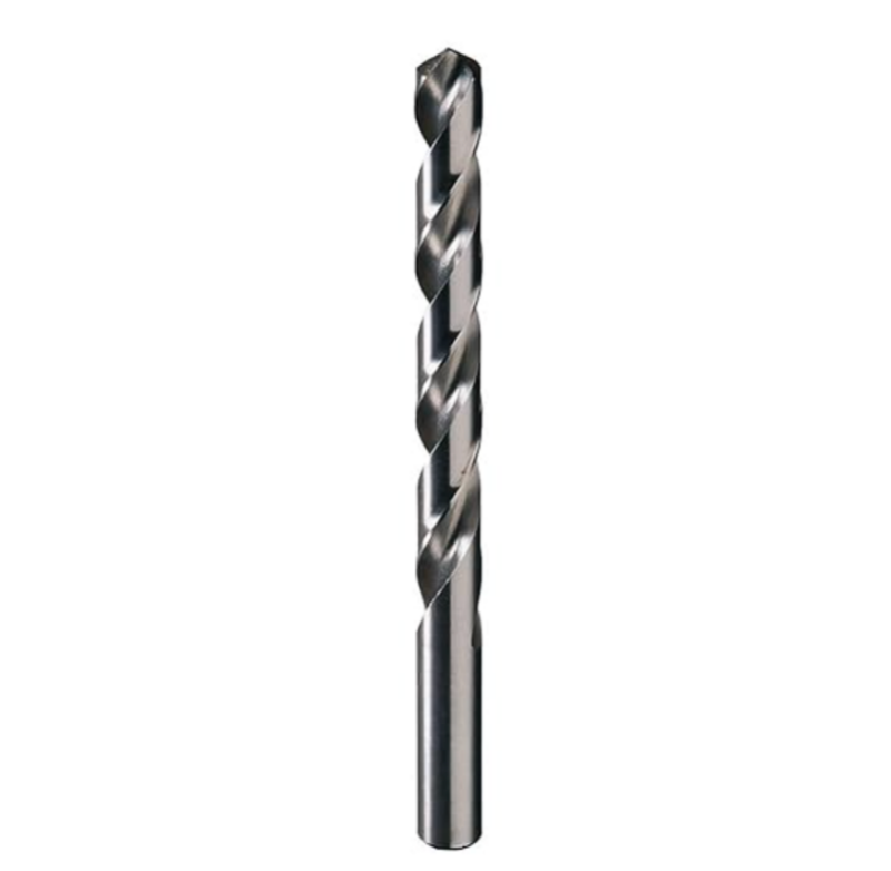
Drill Bits

Drill Bits

Drilling CFRP laminate and mixed stacks

Answers: Exit delamination and oversize holes

Standard: ANSI B94.11M

Jobber Length Drill Bits

Jobber Length Drill Bits

Standard-reach work in aluminium and steel detail parts

Answers: Wander and burr at exit

Standard: ANSI B94.11M

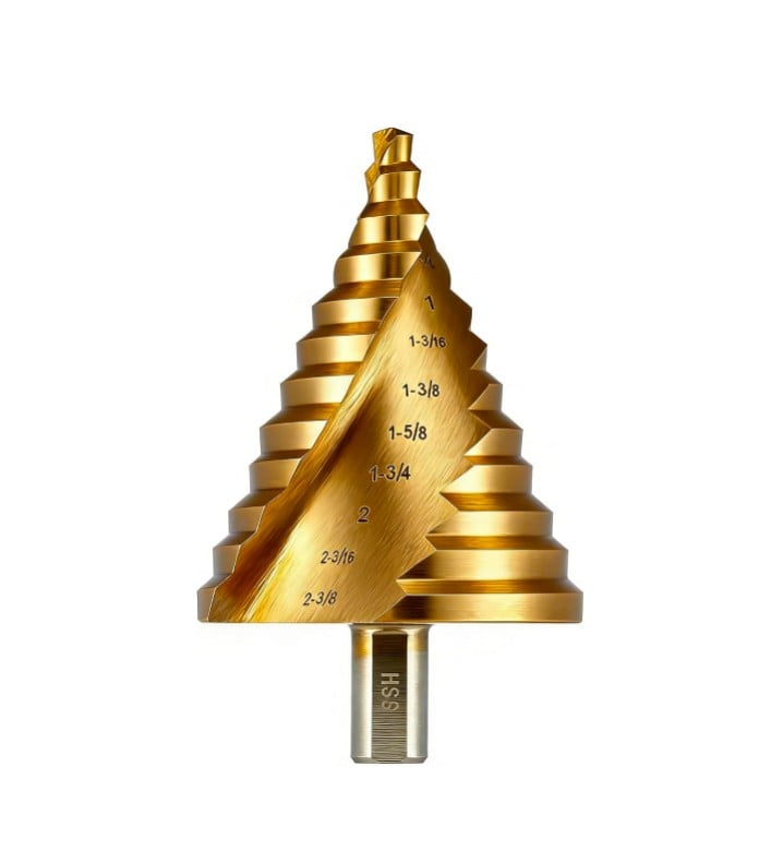
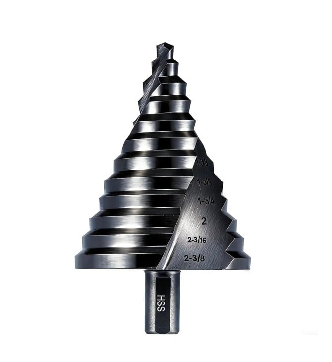
Multi-Stepped Drill Bits

Multi-Stepped Drill Bits

Stepped holes for fastener and shank clearance

Answers: Step wear changing the hole profile

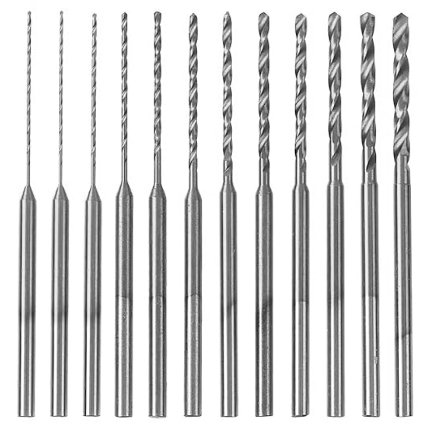
Miniature Straight Shank Drill Bit

Miniature Straight Shank Drill Bit

Pilot holes and small-diameter detail work

Answers: Breakage in long-reach access

Burrs

Burrs

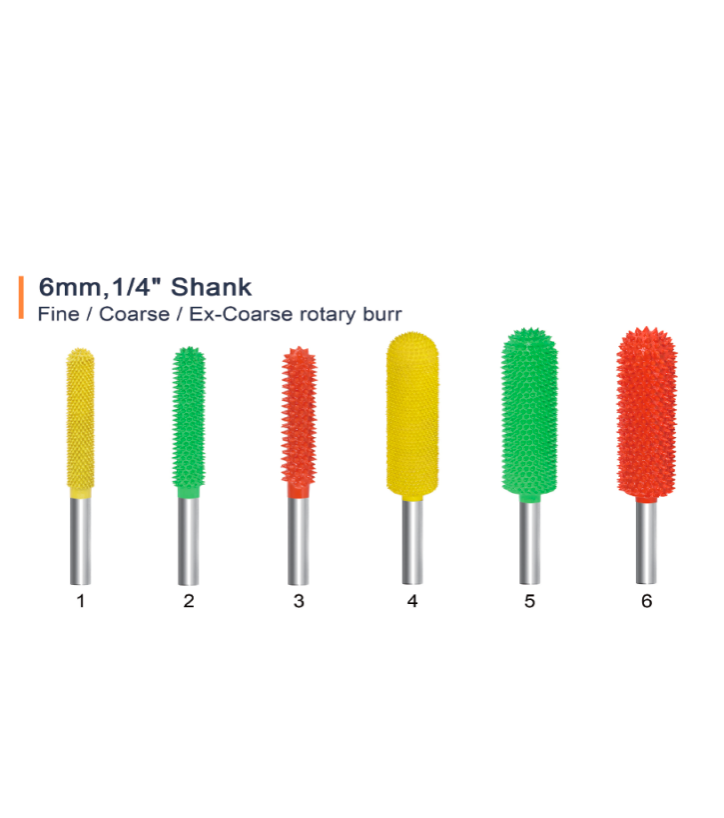
Deburring and edge blending after drilling

Answers: Burr height above the drawing limit

Screw Driver Bits

Screw Driver Bits

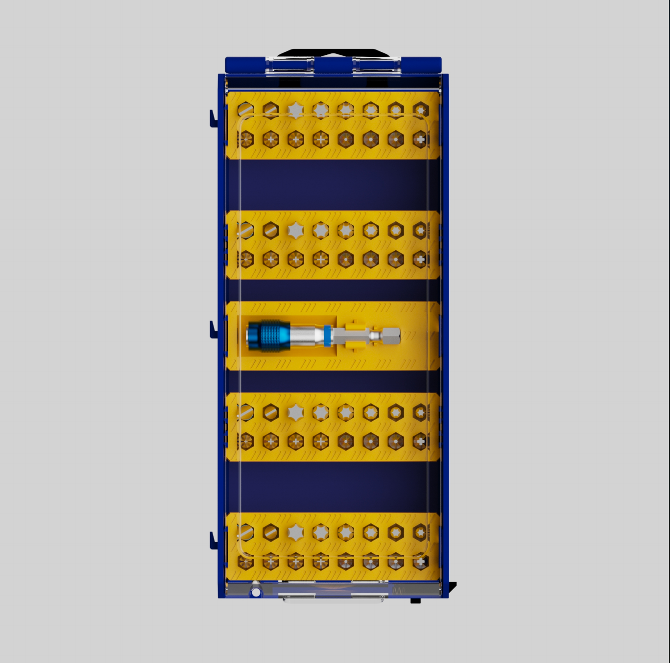
Fastener rundowns during assembly

Answers: Drive-end rounding and cam-out

Standard: DIN 3126-C 6.3 / ISO 1173

Screw Extractors

Screw Extractors

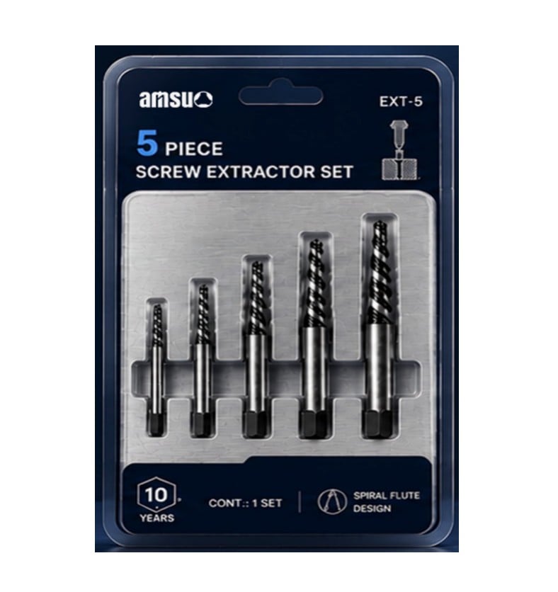
Removing damaged fasteners without damaging the hole

Answers: Hole-wall damage during extraction

Standards & specification

The numbers behind the claims

The table names the parameter, the standard that fixes it, and why a plant's quality function checks it.

Parameter Reference standard What the standard fixes Why the buyer checks it
Drill point geometry ANSI B94.11M Point angles and the split-point form for twist drills The point decides thrust, wander and the condition of the hole at exit
Aircraft drill sizes and shanks NAS 907 Sizes and dimensional requirements for aircraft-quality drills A tool called out to this standard on the drawing has to be made to that basis
MJ thread requirements ISO 5855-1 General requirements for MJ (metric aerospace) threads Aerospace fasteners are specified on the MJ system, not a general metric thread
Fits and limit deviations ISO 286-1 The ISO tolerance system of limits and fits H8 hole call-outs are read from the same tables by both parties
Geometrical tolerancing ISO 1101 How form, orientation, position and run-out tolerances are expressed Hole position and concentricity call-outs must be measurable the same way
Surface texture ISO 4287 How surface roughness parameters are defined and expressed Hole-wall finish is judged on defined parameters
Microindentation hardness ASTM E384 The microindentation hardness test method Hardened layers, including alpha-case regions, are quantified on a stated method
Axial fatigue testing ASTM E466 Force-controlled axial fatigue testing of materials Coupon fatigue results are compared on a stated test method
Salt spray testing ASTM B117 The salt spray apparatus and test procedure Steel components are compared on a stated exposure method
Tensile testing ISO 6892-1 The method for tensile testing of metallic materials Material certification is read on a common basis
Non-destructive testing personnel ISO 9712 Qualification and certification of NDT personnel An NDT result is only as good as the qualification behind it
Penetrant and magnetic particle inspection ASTM E1417 / ASTM E1444 Liquid penetrant and magnetic particle inspection methods Surface defects are found by a defined method
Quality system AS9100 Quality management system requirements for aerospace supply The buyer's audit is conducted against the system the order runs under
How we verify

Organised around method, not around a published figure

In aerospace work the method is part of the specification, so our checks are named before they are performed. Dimensional and geometrical measurement is read against the drawing and the standards that fix it: AS9100 governs the quality system under which the order runs, ANSI B94.11M and, where the drawing calls it, NAS 907 fix the point and shank requirements, ISO 286-1 defines the fit, and ISO 1101 defines the geometrical call-outs. Hole-wall finish, where specified, is measured against ISO 4287.

Where a metallurgical question arises at a hardened or oxygen-enriched layer, it is examined by the microindentation method of ASTM E384. Fatigue and corrosion results, where a programme asks for them, are produced by the axial fatigue and salt spray methods of ASTM E466 and ASTM B117 respectively; surface-defect inspection follows ASTM E1417 and ASTM E1444, with personnel qualified to ISO 9712, and mechanical properties of the material are read against ISO 6892-1. Batch traceability links a delivered tool to its carbide or steel lot, and a first-article record accompanies a special. Where an inspection is not applicable to the item supplied — a penetrant check on a tool that does not carry the feature concerned, for example — we state that rather than reporting an operation that was not performed. Anything beyond the routine record is provided on request.

Customization & delivery

Three levels of engagement, one sequence

Aerospace orders move through the same three levels.

Level 1 — Private label
the buyer's label is applied to tooling already qualified for the stack sequence concerned, with the geometry unchanged and the qualification record intact.
Level 2 — Packaging & specification
the geometry is unchanged while pack count, tool identification and traceability marking are set to the buyer's system, which is what allows a tool to be matched back to a batch during an audit.
Level 3 — Sample- and drawing-driven
a special point geometry, a step, a pilot diameter or a shank modification is ground from the buyer's sample or drawing, supported by a design-for-manufacture review and a first-article inspection report before any repeat order is quoted.Whichever level applies, the sequence runs the same way. The stack sequence, diameters and acceptance criteria are fixed in writing; the drawing or sample is reviewed; the grinding, honing and coating route is set so that each step can be measured against the feature it controls; a first article is inspected against the drawing and the certification package; and the batch is released with a traceability marking that ties the delivered part to its lot. Where a review changes the geometry, the sequence restarts from the revised drawing, and the buyer is told at that point rather than at the delivery date.
Buyer questions

What purchasing teams ask first

How is a tool priced for a specific stack sequence?

Price is quoted per tool against a named sequence and a named diameter, because the substrate, the coating and the point geometry all change with the mix in the hole. A drill for carbon laminate and a drill for carbon and titanium cannot be treated as one line, and quoting them together would hide the difference. Send the sequence, the diameters and the acceptance criterion, and the offer is issued against that basis.

What is the order minimum for a special geometry?

Standard sizes are quoted from an existing route, while a special point geometry or a step that has to be ground for the first time carries its own set-up for the grinding, honing and coating sequence and is quoted separately. We will say at the quoting stage whether a given special can share a set-up with an existing geometry or has to stand alone.

Can we qualify samples against our own coupon test before ordering?

Yes. Samples are supplied against the stack sequence and the acceptance criterion in writing, so the coupon result can be compared with the limits you set rather than with a supplier's summary. Tell us the coupon configuration and the pass criterion, and the sample is quoted against it.

What is the lead time for a production batch?

Standard diameters are released after sample approval, and specials follow once the grinding, honing and coating steps are complete, with coating treated as a separate stage. Where a programme depends on a build rate, the coating schedule and the first-article inspection are the two points to confirm at the order stage, because both sit on the critical path.

Which documents accompany a shipment?

Every shipment carries a batch inspection record covering shank fit, diameter and point geometry against the drawing, together with material certification for the carbide or high-speed steel lot. First-article reports, life records and the delamination or burr-height results are retained per tool family and furnished on request.

Ready to specify it?

Send the stack sequence and the acceptance limit. Tell us the material sequence, the diameter and the burr or delamination limit on the drawing, and we will state which substrate, coating and point geometry is specified for it — and where our range will not meet the limit you have to hold.

Get a Quote in 24 h Request a Free Sample

Get a Free Quote

Our representative will contact you soon.
Email
Mobile
Name
Company Name
Message
0/1000