

Get a Free Quote

Our representative will contact you soon.
Email
Mobile
Name
Company Name
Message
0/1000
Industries
Home> Industries

ENGINEERING

ENGINEERING
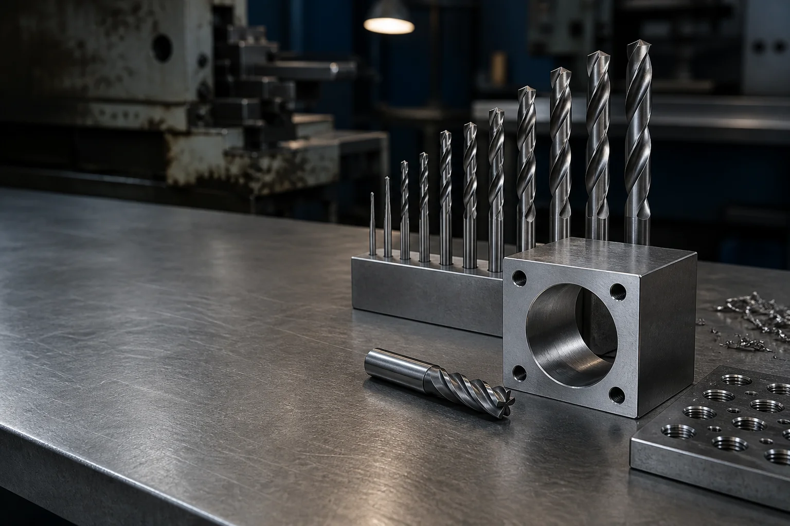
Precision machine shop bench with a row of HSS-E twist drills in a holder and a machined steel block with a bored hole
Engineering

Engineering tool accessories that hold size on hardened, stainless and aluminium work.

Drills, burrs and abrasives specified by workpiece hardness, chip behaviour and tolerance class.

Get a Quote in 24 h Request a Free Sample

A general engineering shop buys cutting tools on three questions: how the tool behaves in the specific workpiece grade, what finish it leaves, and what tolerance band it can hold on a drawing with an h6 or H7 call-out. A tool that lasts well in mould steel may fail in stainless within one part, because the two materials remove heat from the edge in completely different ways. This page sets out which substrate, coating and geometry is specified for each workpiece family, and how each selection can be checked.

Industry snapshot

Four variables that decide the outcome

The distinguishing feature of general engineering is variety: the same machine cuts mould steel in the morning and aluminium in the afternoon, on tooling that is interchangeable within one spindle interface. That variety is what breaks a tool selected on a catalogue grade alone, so the four variables below are read per workpiece family rather than as one shop-wide choice.

Typical equipment
BT40 and HSK-A63 machining centres, CNC lathes with driven tooling, sinker and wire EDM, turret mills, radial-arm drills, surface grinders, tool and cutter grinders.
Materials processed
1.2311 and 1.2738 mould steel, 1.2344 hot work steel, 1.2379 cold work steel, 42CrMo4, 1.4301 and 1.4404 stainless, GGG40 ductile iron, 6061 and 7075 aluminium, Inconel 718, Ti-6Al-4V, unfilled and glass-filled thermoplastics.
Governing standards
DIN 338 and DIN 340 for twist drills, DIN 1835 for parallel shanks, ISO 286-1 and ISO 286-2 for fits, ISO 1101 for geometrical tolerancing, ISO 4287 for surface texture, ISO 68-1, ISO 261 and ISO 965-1 for metric threads, ISO 2768 for general tolerances, ISO 6508-1 for hardness.
Failure modes seen
Edge chipping on interrupted cuts, built-up edge on aluminium, flank wear raising roughness, drill wander on angled entry, breakout at a cross-hole exit, collet slip and tool pull-out, microcracking in a recast layer, cost per cavity rising through insert consumption.
Operating challenges

Three failures that cost lines money

Each challenge states what goes wrong, then the geometry or material decision that answers it.

Challenge 1

Interrupted cuts chip the cutting edge in hardened steel.

Cutting a hardened workpiece with a general-purpose edge produces chipping rather than gradual wear, because entry and exit impacts concentrate at the edge radius. Where the edge chips, it scrapes instead of cutting, so the finishing allowance has to be taken again at a lower feed and the part takes longer to finish than the route allowed for. The same tool in the same holder on unhardened mould steel gives no such result, which is why the substrate is selected per workpiece rather than per shop.
Amsuo response

Interrupted-cut chipping → Drill Bits ground from a micrograin carbide grade with an AlCrN coating.

Grain size and cobalt content are balanced so the edge has the hardness to resist abrasive wear in hardened and alloy steel while keeping enough transverse rupture strength to absorb entry and exit impacts. The AlCrN coating holds its oxidation temperature above the range reached in dry cutting of hardened steel, so the edge is protected by a stable layer rather than by an oxide that forms and spalls. A defined edge hone radius removes the sharp, brittle edge that chips first.
Challenge 2

Built-up edge on aluminium smears the finish.

Cutting aluminium with a geometry designed for steel produces a built-up edge that welds to the rake face and then breaks away, taking particles of the workpiece with it. Where that happens, the surface reads rougher than the drawing call-out and a polishing operation appears in the routing that was never planned. On higher-strength aluminium the same mechanism shows up as dimensional drift, because the built-up edge changes the effective cutting radius from part to part.
Amsuo response

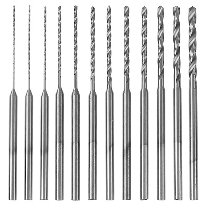
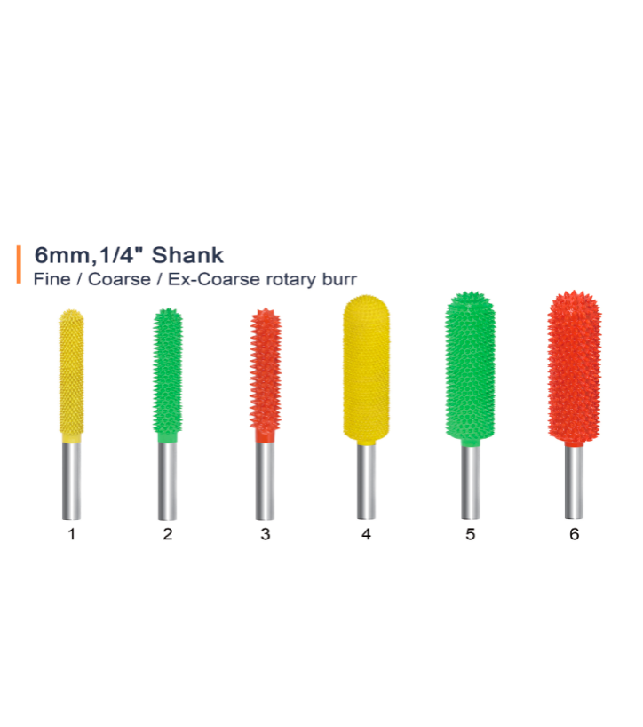
Built-up edge on aluminium → Miniature Straight Shank Drill Bit and Burrs with a polished cutting face.

The cutting face is polished so there is no mechanical key for aluminium to weld onto, and flute and tooth geometry is set to move the chip away from the edge so it is not re-cut. Where a coating would raise friction against a soft, reactive workpiece, the tool is left uncoated on the cutting face and treated only on the flank, which keeps the built-up edge from forming without giving up flank wear resistance.
Challenge 3

A drill wanders on angled entry and breaks out at a cross hole.

Entering a curved or inclined surface with a standard point lets the tip walk before the flutes are engaged. Where the hole lands off position on a pitch circle, the part is either reworked or scrapped, and that decision is taken at the machine rather than at inspection. At the exit of a cross hole the same geometry pushes the last wall thickness out rather than cutting it, leaving a burr that has to be removed before the part can be measured.
Amsuo response

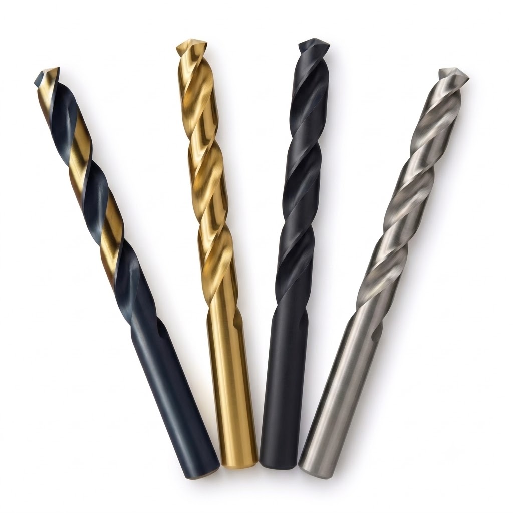
Drill wander and breakout → Jobber Length Drill Bits with a split point and an h6 ground shank.

Web thinning behind the split point reduces the axial thrust needed to start the cut, which is what stops the tip walking on an inclined surface before the outer corners engage. A cobalt-alloyed high-speed steel raises hot hardness so the edge survives the higher temperatures in stainless without rapid flank wear, and long-reach versions are ground to the same point geometry rather than to a blunter compromise. The shank is ground to the h6 fit class of ISO 286-1, which gives a repeatable grip in a collet chuck and removes the pull-out risk that comes from a shank that is undersized or oval.
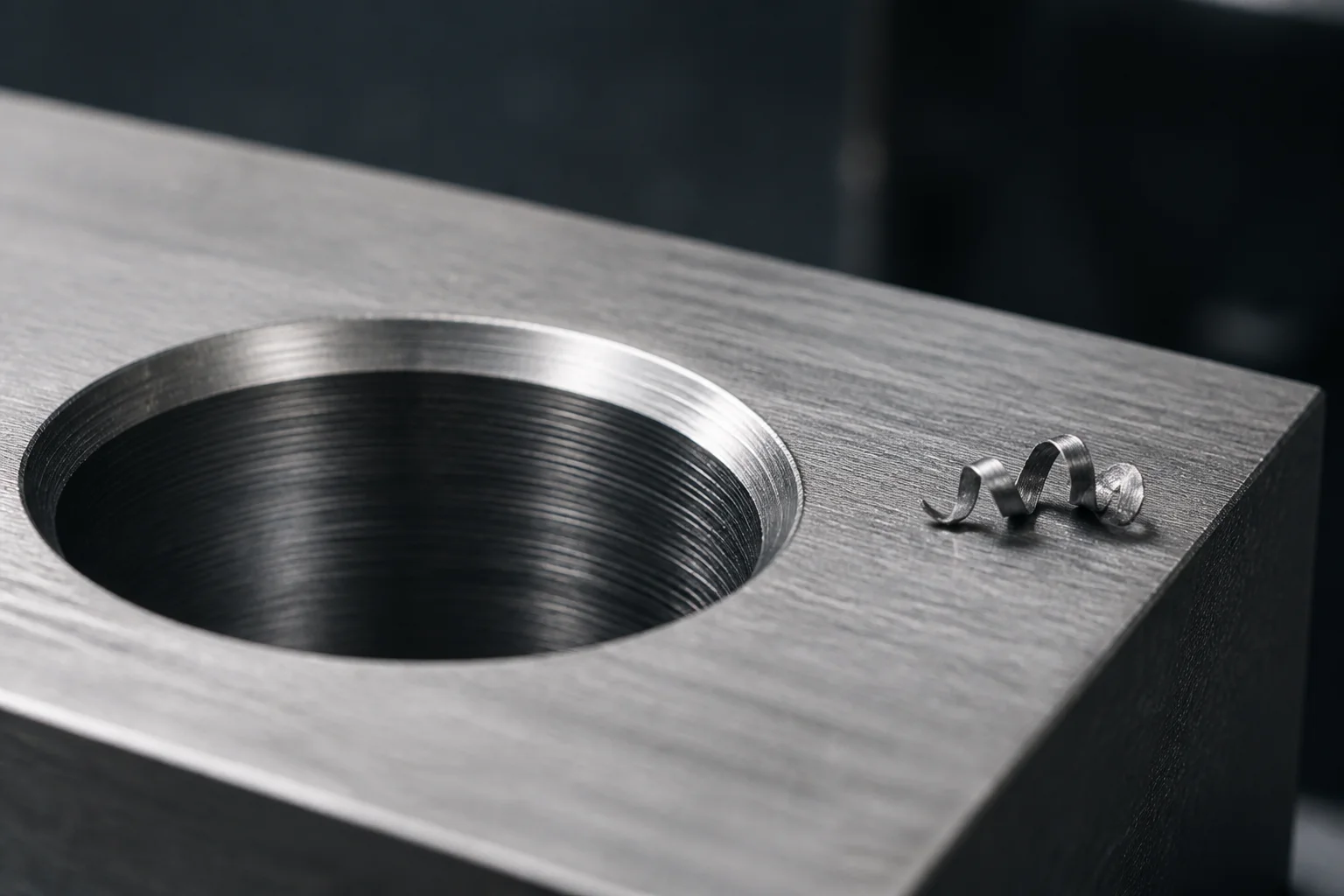
Macro view of a reamed bore through a steel block showing fine tool marks and a chamfered entry edge
Product families

The families that map to this application

Drill Bits

Drill Bits

Drilling hardened, alloy and stainless workpiece families

Answers: Edge chipping on interrupted entry

Standard: DIN 338

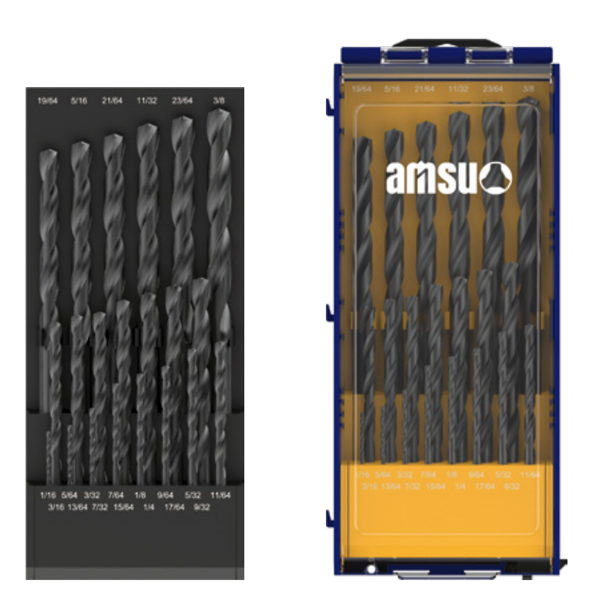
Jobber Length Drill Bits

Jobber Length Drill Bits

General-purpose drilling to a drawing tolerance

Answers: Drill wander and breakout at exit

Standard: DIN 338

Taper Shank Drill Bits

Taper Shank Drill Bits

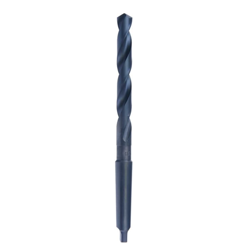
Large-diameter work on mill and radial-arm machines

Answers: Shank slip in the machine socket

Standard: DIN 1835

Miniature Straight Shank Drill Bit

Miniature Straight Shank Drill Bit

Small-diameter work, cooling channels and pilot holes

Answers: Breakage from excessive thrust

Burrs

Burrs

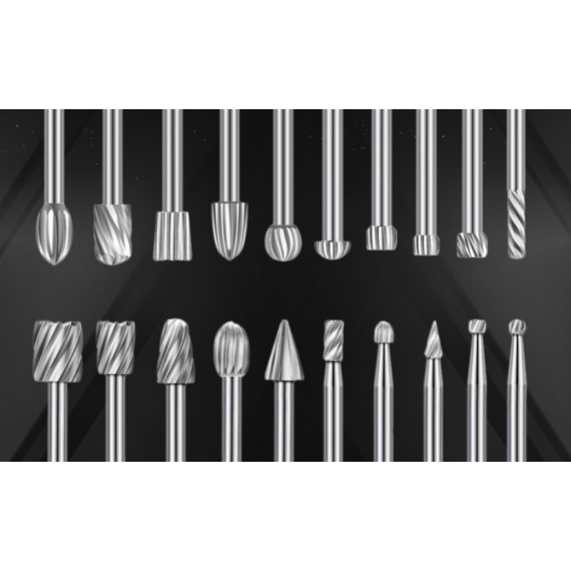
Deburring, blending and edge preparation

Answers: Burr left at a cross-hole exit

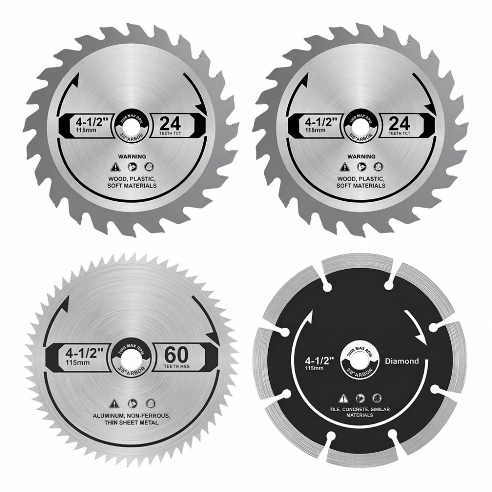
Circular Saw Blades

Circular Saw Blades

Cutting bar and section stock to length

Answers: Tooth damage from hard spots

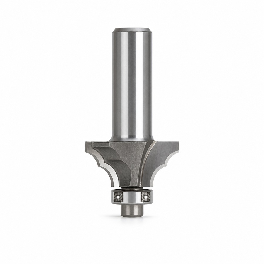
Router Bits for Wood

Router Bits for Wood

Cutting tooling board and pattern material

Answers: Edge wear from abrasive fillers

Standards & specification

The numbers behind the claims

The table names the parameter, the standard that fixes it, and why a plant's quality function checks it.

Parameter Reference standard What the standard fixes Why the buyer checks it
Twist drill dimensions DIN 338 / DIN 340 Diameter series and proportions of parallel-shank twist drills A drill has to be interchangeable in a holder already set up for the job
Shank form of parallel-shank tools DIN 1835 The shank forms used for tools with a parallel shank The shank form decides how the tool is held and whether it can slip
Fits for holes and shafts ISO 286-1 / ISO 286-2 The ISO tolerance system and the tables of limit deviations h6 and H7 call-outs are read from the same tables by both parties
Hardness testing ISO 6508-1 The Rockwell hardness test method and its verification Substrate and treatment figures are only comparable when the method is named
Surface texture ISO 4287 How surface roughness parameters are defined and expressed A finish call-out has to mean the same thing on both sides
Geometrical tolerancing ISO 1101 How form, orientation, position and run-out tolerances are expressed The measurement method must match the drawing call-out
General tolerances ISO 2768 Default tolerances where a drawing does not state one Parts are judged on a stated default rather than an assumed one
Metric thread profiles ISO 68-1 / ISO 261 / ISO 965-1 Basic thread profile, general plan and tolerances of ISO metric threads Tapped features and threaded shanks are judged on the same basis
How we verify

Organised around method, not around a published figure

Inspection starts with the drawing. Dimensional and geometrical checks are read against the standard that fixes the feature: DIN 338 and DIN 340 for twist drill proportions, DIN 1835 for parallel shanks, ISO 286-1 and ISO 286-2 for fit classes, ISO 1101 for form and position, and ISO 2768 where the drawing carries no individual tolerance. Hardness is verified by the method named in ISO 6508-1, and surface finish, where it is called out, is measured against the parameter definitions of ISO 4287. Threaded features are checked against the metric thread standards named above.

Every lot is traceable to the material certificate for its steel or carbide stock, so a query raised against a delivered tool can be answered from the batch record rather than from recollection. Where inspection beyond the routine batch check is required — a coating examination, for example — it is carried out on request and the result is reported against the method used. Where a check does not apply to a family, we say so rather than reporting it.

Customization & delivery

Three levels of engagement, one sequence

Tooling for a job shop is usually specified by the workpiece rather than by the brand.

Level 1 — Private label
the buyer's label goes onto tooling already qualified for the workpiece family concerned, with the geometry unchanged.
Level 2 — Packaging & specification
the geometry stays and the pack, size marking and tool identification change, which matters where a shop issues tools from a crib and has to trace an edge back to a batch.
Level 3 — Sample- and drawing-driven
a special step, corner radius, pilot diameter or shank modification is ground from the buyer's sample or drawing, supported by a design-for-manufacture review returned before the first article is produced. Development at level three draws on our own design work, which includes a design patent for an adaptive hex-shank tool accessory.A special starts from four inputs: the workpiece designation, the operation, the machine interface and the tolerance that has to be held. The drawing or sample is reviewed, the grinding and coating route is fixed, and a first-article report covering geometry and hardness is issued before the geometry is released for repeat production. Where the review identifies a geometry change, the route restarts from the revised drawing.
Buyer questions

What purchasing teams ask first

How is a cutting tool priced for a specific workpiece?

Price is quoted per tool against a named workpiece grade, because the substrate and the coating change with the material and the two cannot be treated as one line item. A tool for hardened tool steel and a tool for soft aluminium differ in grade, in edge preparation and in coating, and quoting them at one figure would hide that. Send the material designation and the operation, and the offer is issued against that basis.

What is the smallest order for a special geometry?

Catalogue sizes are quoted from a stock route; a special ground geometry needs its own grinding and coating set-up and is quoted separately. Once a geometry is established it can be run alongside other batches, and we will say at the quoting stage whether a given special can share a set-up with an existing geometry or has to stand alone.

Can we run a trial tool before committing?

Yes. Trial tools are supplied against a stated workpiece grade and cutting condition, so the result can be compared with the data you already hold rather than with an unrelated job. Tell us the machine, the fixture and the acceptance criterion, and the trial tool is quoted against that.

What is the lead time for a production batch?

Standard sizes are released after sample sign-off, and specials follow once the grinding and coating steps are complete, with coating treated as a separate stage in the sequence. Where a job depends on a fixed date, the coating schedule is the point to confirm at the order stage rather than after the tools are ground.

Which documents accompany the tools?

Standard sizes ship with a batch inspection record covering shank fit, hardness and key dimensions. Specials ship with a first-article report that adds the ground geometry against the drawing. Coating records and workpiece-specific life records are filed per tool family and issued on request.

Ready to specify it?

Send the material designation and the operation. State the grade, the machine and the tolerance call-out, and we will name the substrate, coating and edge preparation specified for it — and tell you where our range will not hold the tolerance you need.

Get a Quote in 24 h Request a Free Sample

Get a Free Quote

Our representative will contact you soon.
Email
Mobile
Name
Company Name
Message
0/1000